What exactly is Business Process Modeling Notation (BPMN)?
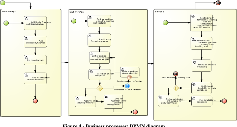
BPMN, elongated as Business Process Modeling Notation is precisely an open standard for drawing a business process. It is also is known a business process model & notation. It is similar to a flowchart and represents the participants, options, and process flow using standardized graphics. The diagrams are created to be intricate but simple for readers without technical knowledge.
This makes it possible for analysts, executives, and technical implementation employees to all use the same graphic to promote communication and understanding among groups. There is no direct correlation between a BPMN diagram and any one implementation.
Key Benefits and Purpose
Apart from participants, BPMN is also intended to provide other stakeholders in any business process with an understandable visual depiction of the processes to increase understanding. At a deeper level, it is directed at those who will carry out the process, providing enough information to allow for accurate execution. It gives all stakeholders, process participants, business analysts, technical developers, the managers, as well as outside teams and consultants—a consistent language that they can all use. This includes both technical and non-technical stakeholders. Ideally, BPMN closes the break between execution and process intention by giving enough clarity and specificity regarding the order of business operations.
Diagrams can often be simpler to understand as compared to narrative prose. It makes it simpler to communicate and work together to achieve the objective of an effective process that yields high-quality results. Furthermore, it facilitates the communication that results in the Extensible Markup Language (XML) documents required to carry out various activities. Business Process Execution Language (BPEL) for Web Services, is one of the key XML standards.
The Use of Business Process Modeling Notation
BPMN is fundamentally made up of a set of rules and symbols for connecting those symbols to form a business process. A private or public process can be represented by these diagrams, which are known as business process models. The primary goal of BPMN was to aid in bridging the frequently present communication gaps between the different departments within a company or firm. Business Process Management (BPM) initiatives frequently employ BPMN.
Although BPMN is not directly related to any particular workflow implementation, it is mostly used to depict programmed processes clearly. A business analyst might, for example, draw a BPMN diagram to illustrate a business process. That diagram can be implemented by a programmer with the help of business orchestration software’s Business Process Execution Language (BPEL) code. A diagram of BPMN of the implemented process can then be produced by the program for executive review.
Who performs Business Process Modeling?
Simple, hand-drawn diagrams can be used for business process modeling, as well as more complex ones with expandable sections that provide enough implementation information. At its most advanced, BPMN is performed by qualified analysts. The OCEB 2 designation, elongated as OMG-Certified Expert in the field of BPM 2.0, is one of five BPMN 2.0 certifications offered by the Object Management Group (OMG). The business track is one, and the technical track is another. In the same manner that Unified Modeling Language (UML) standardized software modeling, OMG hopes that BPMN 2.0 will standardize business process modeling.
BPMN demands time and effort, but the benefits in terms of improvement and knowledge can be enormous. Version 2.0 improves on earlier iterations by offering a more comprehensive standard set of notations and symbols, enabling additional information for those that require it.
Creating a cycle of continuous development is the premise underlying business process management. Model, implement, execute, monitor, and optimize are the steps. BPMN diagrams are crucial for this.
Outline on Icons of Business Process Modeling Notation
One may compare BPMN with a Graphic Programming Language (GPL). In the diagram, every icon has a clear purpose and significance. Each of these icons denotes a stage or activity in the workflow.
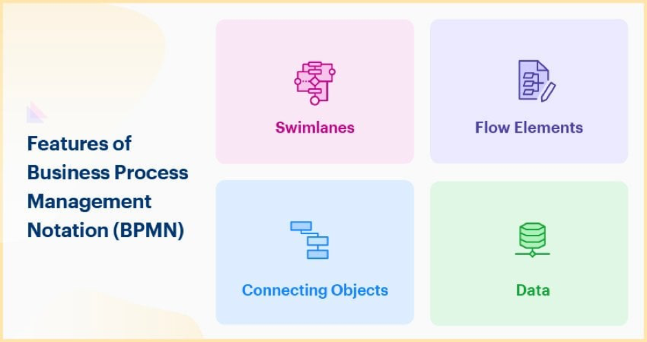
The key sequence and process flow are created by connecting the flow objects. Flows, Events, Activities, and Gateways are the divisions within them.
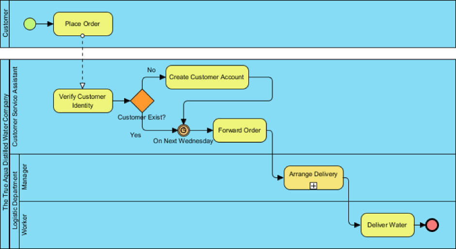
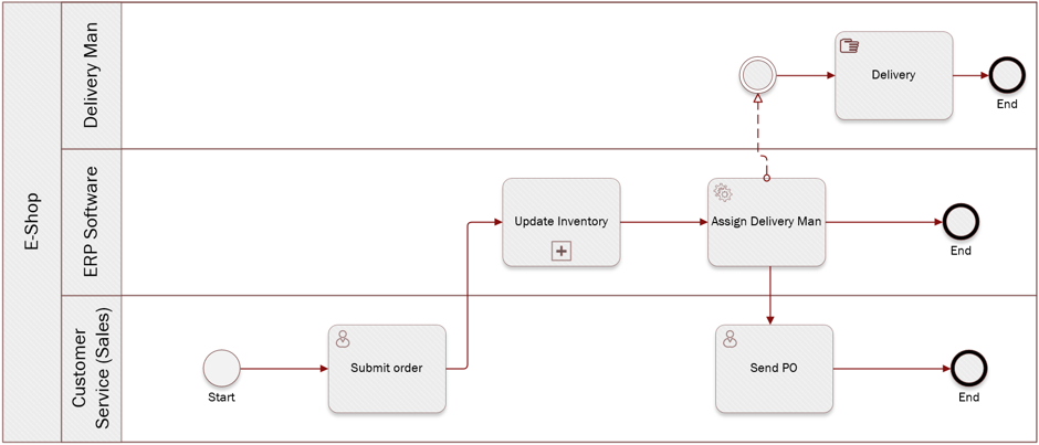
- Event: An event denotes a flow interruption. The symbol for it is a circle. Start events, immediate events, and end events are the different categories of events.
- Gateway: A diamond-shaped splitting point in a flow. They may be complex gateways, branching parallel activities, exclusive or inclusive decisions, or decisions that affect both parties.
- Activity: Effort put forth during a process symbolized by a smooth-edged rectangle. They could be a single discrete task or a composite process that incorporates several different process flows.
To show the sequence, linking items are flow objects connected by directional arrows. There are three different categories of connected objects: Associations, Sequence Flows, and Message Flows.
- Sequence Flow: To show the order, objects with just one source and one destination are grouped in a solid line.
- Association: A dotted line links the artifacts with objects.
- Message Flow: A dashed line illustrates the communication path among parties.
Swimlane is actually a structure used to divide activities. Swim lanes can be vertical or horizontal. A swimlane can be either a lane or a pool.
- Lane: A box that can be used to depict internal divides inside a pool. Using the manager and associate roles in a corporation as an example.
- Pool: A box signifying a distinct entity, as a different division or company. Pools can be drawn as a “black box” for outside participants without internal process representation.
In a process, data objects are the input, output, and intermediary information. They are shown as a file having one of its corners folded.
Clarifying information that is added to a diagram but does not change the flow is known as an artefact. Examples include a note for text annotation and a dashed box to show a grouping.
Sub-Models inside a BPMN Diagram
Both technical and non-technical audiences can be reached by using diagrams. Sub-models make it simple for the various viewers to distinguish between the diagram’s numerous portions and identify the ones that apply to them the most. The several sub-model kinds are:
- Private Business Processes: These don’t cross organizational boundaries or pools since they are internal to a particular entity.
- Abstract Business Processes: These take place between a process or participant that is private or internal and another. The private process’s communication requirements are displayed to the outside world through the abstract process. It doesn’t display the private/internal procedure in its entirety.
- Collaboration Business Processes: These demonstrate how two or more commercial enterprises interact.
Other diagram types
There are three additional diagram types in BPMN 2: Dialogue, Collaboration, and Choreography.
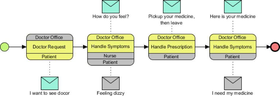
- Choreography Diagram: Demonstrates the interactions among two or above candidates. Sub-choreographies may be added to it as well.
- Collaboration Diagram: This demonstrates interactions among two or above processes while using several pools. A collaboration diagram may utilize any concoction of pools, processes, and choreography.
- Conversation Diagram: Generally speaking, this is a condensed form of a collaboration figure. A series of connected exchanges of messages in a business process are displayed. Sub-conversations could be used to extend it.
Closure
Although BPMN is an effective tool for illustrating business processes, its scope is constrained and additional standards must be used to implement it or to include different kinds of activities. Decision Models and Notations are the best for decision flows.
